 |
|
|
|
|
Pinouts de MotherboardsLos siguientes son los esquemas de pinout (asignación de patillas) de los diversos conectores de motherboard: USBPINS: Power (+5 V), D-, D+, Ground
USB con soporte Flash DrivePINS: Power (+5 V), D-, D+, Ground, LED#
HD Audio y AC97 AudioPINS: Port1L, Port1R, Port2R, Sense_Send, Port2L, Ground, Presence#, Sense1_Ret, Sense2_Ret, MIC, MIC_BIAS, FP_OUT_R, AUD_5V, FP_OUT_L, AUD_GND, FP_RETURN_R, FP_RETURN_L
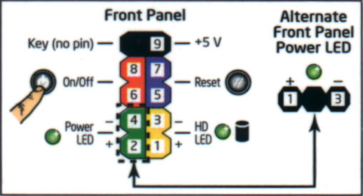
Front PanelPINS: On/Off, Power LED, +5V, Reset, HD LED
Puerto paraleloPINS: Ground, SLCTIN#, INT#, FAULT#, AUTOFD#, SELECT, PERROR, BUSY, ACK#, PD7, PD6, PD5, PD4, PD3, PD2, PD1, PD0, STROBE#
Puerto SeriePINS: DCD, TXD#, Ground, RTS, RI, RXD#, DTR, DSR, CTS
SPDIFPINS: Ground, S/PDIF Out, +5 VDC
|
|


Copyright © 2003-2025 Moraldo Networks. Todos los derechos reservados.